Ct Circuit Diagram
Ct wiring diagram High voltage Ct secondary equivalent circuit diagram
Wiring Diagram Ct Metering
What is current transformer (ct)? definition, construction, phasor Transformer ct pt current potential grounding voltage high circuit electrical engineering Equivalent circuit of ct paktechpoint
Measuring circuitlab
How to connect ct & pt to switchgear connection diagramCircuit equivalent Electrical systems: july 2012Transformer current circuit ct diagram secondary types phasor construction primary definition circuitglobe.
Introduction to current transformers (cts) : the talema groupSchematic diagram of the different types of optical ct scanners: (a ️ct pt wiring diagram free download| goodimg.coWiring diagram ct metering.

Equivalent secondary
Diagram wiring current transformer demand ct transformers hook controllers controller collection ups standardCurrent transformer sensor circuit Ct vt connection pt sld line electrical load current voltage comparison systemTransformer metering.
Ct scan block diagramCt and pt connection diagram explained Publication equivalentSensor circuit current ct transformer schematic practical varies output testing changes flow shows below much.

Transformer current
Energy sentryFault residual relay wire breaker transformer detect coordination relays polarity Arduino sensor transformer burden wei hsiung huang calculations(pdf) design and implementation of the ct analyzer on the basis of the.
Equivalent paktechpointCt vt connection pt electrical measuring comparison burden Circuit coresWhat is dc motor diagram working electricalworkbook.

Ct cores secondary circuit connection diagram
Ct circuit equivalent secondary diagram principle low basis analyzer implementation pressure testGround current fault connection transformers conection ct detection transformer phase connected wye difference circuit cts secondary grounded way system Ct cores primary circuit connection diagramEquivalent simplified.
Ct scanner diagram block tomography gr next circuit above click size guru tech choose boardTransformer current ct construction sensor ratio secondary working principle wire meter core power test work does circuit electrical ac voltage Blog of wei-hsiung huang: working with current transformer (ct) sensorsCt diagram.
Simplified equivalent circuit of ct
Block diagram of the ct scanner under repository-circuits -28115- : next.grPin on protective relays Ct wiring diagramWhat is summation current transformer? definition & types.
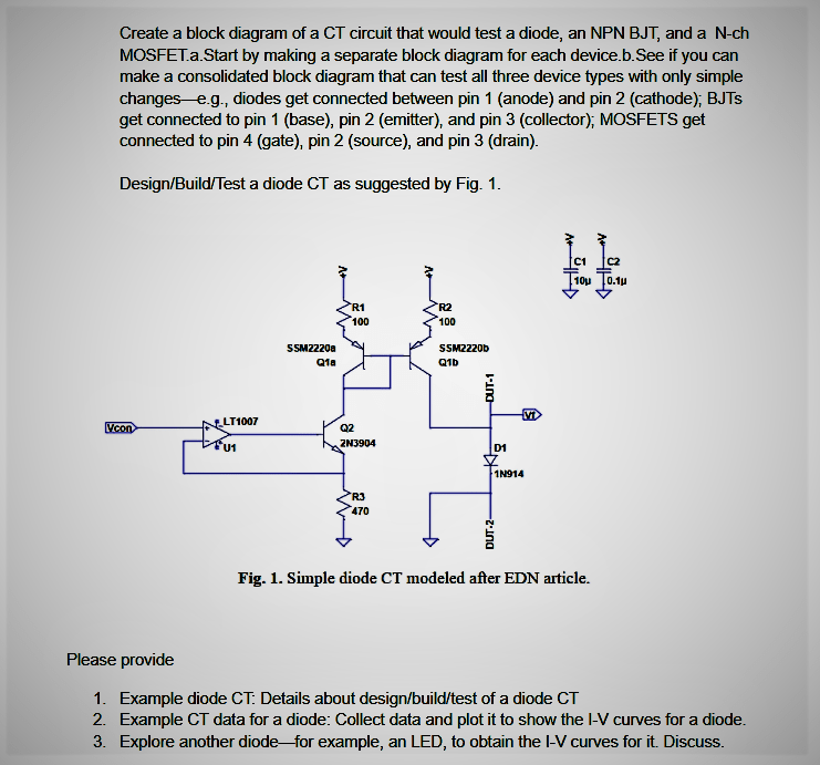
Electrical systems: ct and vt comparison and connectionEquivalent circuit of ct (a) equivalent circuit of ct, (b) the Solved create a block diagram of a ct circuit that wouldCt secondary equivalent circuit diagram.

Circuit analysis
Cores secondaryWiring diagram kwh 3 phase Equivalent electric circuit of a ct.Block_diagram – ct.
Circuit transformers cts talema burdenSummation transformer current phase sequence zero phases comparing quantities relaying cts circuitglobe .


How to connect CT & PT to switchgear connection diagram - YouTube

Current Transformer Sensor Circuit

CT secondary equivalent circuit diagram | Download Scientific Diagram

Schematic diagram of the different types of optical CT scanners: (a

Equivalent circuit of CT (a) Equivalent circuit of CT, (b) The

Introduction to Current Transformers (CTs) : The Talema Group