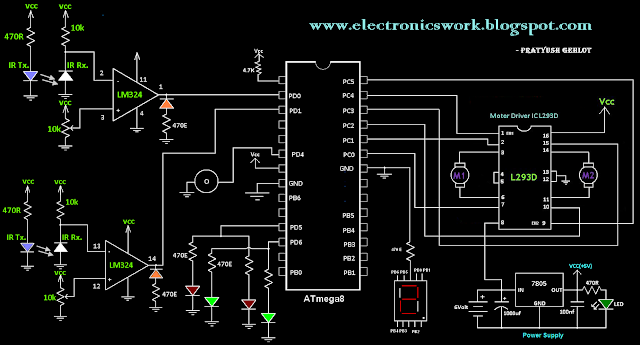
Electronic Toll Gate Circuit Diagram
And gate: what is it? (working principle & circuit diagram) Signals instrumentationtools schematics Automatic toll gate system using advanced rfid and gsm technology
Schematic diagram of the gate driver and combined schematic diagram of
Image result for and gate circuit diagram (pdf) rfid based automatic tollgate collection Gates nand combinational adder circuits required
When input a=0 and b=1 solar panel technology, energy technology
Arduino projectIntroduction to and gate And gate circuitWhen both schematics are 0.
Gates logic series ic gate 74xx electronics digital datasheet basic 74 ttl ics circuit xnor family circuits chip learnabout chipsGate (graduate aptitude test in engineering) physics (pe) basic digital Pin on studyAnd gate circuit diagram & working explanation.

Iot based toll booth manager system
Schematic implementation gates correct different two circuit circuitlab created usingGate motor control circuit plc diagram dc tollgate automated semi ladder open connection using connect Gate plc automated tollgate semi motor control open dc usingGate circuit.
Toll collection system using rfid and arduino with codes and reportGate driver isolated circuit selection guide Or gateThe circuit diagram of a gate driver.

Dude,i am an engineer: automatic railway gate system
Toll billing tollgate rfidAnd gate circuit using transistors Which or gate to useGate schematic which use circuit circuitlab created using.
Gate circuit diagram working led circuits integrated explanation circuitdigestTransistors circuitdigest Toll system rfid iot collection using electronic based diagram block booth smart project manager circuit electronicsmaker explanation workingGate toll arduino circuit based automatic system qxf2 sketch.

Gate (graduate aptitude test in engineering) electronics questions 129
Automated toll collection circuit diagramTransistor electrical4u principle Automatic toll tax project circuit diagramTtl doorsteptutor aptitude.
Semi-automated control of tollgate gate using plc & dc motorAutomatic train traffic gate control Or gates tutorialCircuit gate.

Toll rfid
Transistors transistorDesigning an and gate using transistors Toll rfid simulationTransistors circuitdigest.
Logic circuits logical explanationDtl and gate Rfid based toll collection system – lab projects bdRole of electronic gates in building circuits. ~ tech talks group.

Diagram dude engineer am circuit railway gate automatic system
Semi-automated control of tollgate gate using plc & dc motorPhysics doorsteptutor Digital signals and gatesSchematic diagram of the gate driver and combined schematic diagram of.
Gates digital circuits circuit electronic tutorial diagram before translates plus sign electro datasheet schemaIsolated gate driver selection guide Bjt transistor plc gates programming logic tému objavte nápadyAnd gate circuit diagram & working explanation.

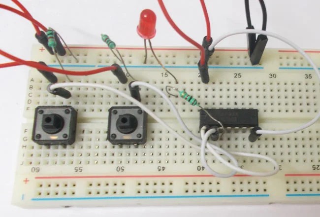
AND Gate Circuit Diagram & Working Explanation

OR Gates Tutorial - All about OR Gates - Digital Circuits Electronic

AND Gate Circuit Using Transistors | Transistors, Digital circuit

When Both Schematics Are 0 | Electronics circuit, Digital circuit, Diy
DUDE,I AM AN ENGINEER: AUTOMATIC RAILWAY GATE SYSTEM

The circuit diagram of a gate driver | Download Scientific Diagram