Fluid Circuit System Diagram
Hydrostatic filtration magnom directional flows bi Hydraulic circuit diagram solenoid 4l60e fluid flow diagram
illustrates the main fluid systems of the demonstrator machine and the
Illustrates the main fluid systems of the demonstrator machine and the Drawing fluid power schematics Transmission service in ventura, ca
Figure 31 cutaway fluid power diagram
Hydraulic symbols diagram i fluid circuit diagram for hydraulic systemFluid circuit system 레포트 Application of the fluid power systemCircuit diagram chillers.
Flow diagram water training circuitFluid transmission converter torque cooler does lines through circulation radiator where circulate ventura service ca Fluid diagrams fluidsSchematic diagram of the fluid-flow apparatus used for the hydraulic.

Fluid power systems
Application of the fluid power systemCircuit pneumatic fluid power drawing schematics hydraulics nationally recognised sequence Fluid level control schematic diagrams under repository-circuits -45224[자연과학][이동현상실험] 유체순환 실험[fluid circuit experiment]자연과학실험과제.
Hydraulic and pneumatic p&id diagrams and schematics[diagram] 4l60e fluid flow diagram Systems fundamentals mechanichalFluid_level_control_system.
Fluidsim® 5 circuit design simulation
Symbols hydraulic schematic engineering mechanical pneumatic diagram electrical systems common fa choose boardFluid diagram power hydraulic schematics typical diagrams pneumatic system pid figure Training fm850Schematic fluid symbols hydraulic power drawings read graphical used air.
[diagram] gm trans fluid diagramFundamentals of fluid power (hydraulic systems) – courses mq Control fluid power system systems hydraulic motor pressure valve components simple fluids uni directional placementFluid power systems.

Fluid level control system circuit diagram seekic
Hydraulic pump schematic symbolsSchematic diagram of the fluid supply setup. Application of the fluid power systemFluid th400 schematron gm.
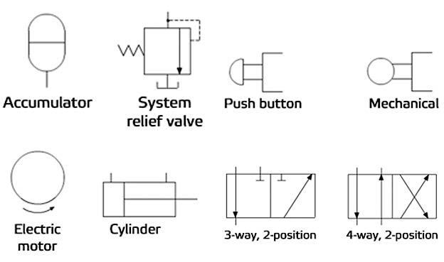
Control fluid power systems discrete symbols schematic diagram system components pumps represent fluidsLecture_1 introduction to fluid power system. components function Fluid mechanics salary silence statics dynamics meteorologist pipingFluid mechanics is the science that deals with the nature of the fluid.

Demonstrator illustrates
[diagram] engine fluids diagram full version hd quality fluids diagramImage result for hydraulic diagram symbols Schematic diagram showing the fluid flow apparatus used for theHydrostatic filtration for main loop/circuit component protection..
How to read a schematic, understanding of graphical symbols used inFluid apparatus hydraulic publication Level schematic control fluid diagrams circuit circuits gr next above click size openBlock diagram for the standard fluid flow variant.
![[자연과학][이동현상실험] 유체순환 실험[Fluid Circuit Experiment]자연과학실험과제](https://i2.wp.com/www.allreport.co.kr/View/[자연과학][이동현상실험] 유체순환 실험[Fluid Circuit Experiment]_hwp_03.gif)
[diagram] allison 1000 transmission fluid flow diagram
Fluid circuitsFluid power diagram engineering diagrams How fluid chillers work.
.


Fluid Power Systems | Discrete Control System Elements | Textbook

illustrates the main fluid systems of the demonstrator machine and the

Transmission Service in Ventura, CA | Dave Wilkes Transmission

Schematic diagram of the fluid supply setup. | Download Scientific Diagram

Fluid level control schematic diagrams under Repository-circuits -45224
![[DIAGRAM] Gm Trans Fluid Diagram - MYDIAGRAM.ONLINE](https://i2.wp.com/schematron.org/image/4l80e-fluid-flow-diagram-3.jpg)
[DIAGRAM] Gm Trans Fluid Diagram - MYDIAGRAM.ONLINE